Profile family · Compression seal
Kerf-in bulb Weatherstrip Profile
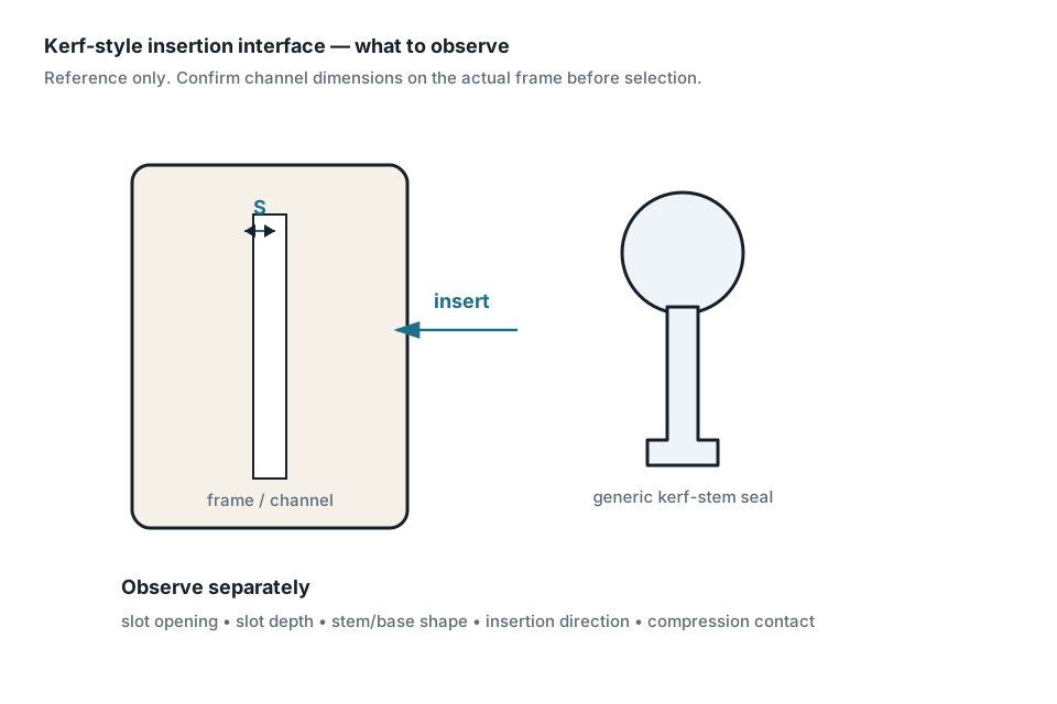
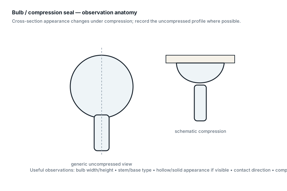
End-view shows a compressible bulb joined to a narrow insertion stem/base that seats in a cut groove. This page identifies a generic family and the measurements needed to compare sites; it does not identify an exact replacement.
Generic profile family supportedExact replacement fit not checkeddoor · window
Identification snapshot
- Subtype
- Kerf-in bulb
- Contact mode
- compression
- Seal body
- bulb
- Mount/interface
- kerf / push-in stem
- Common terms
- kerf-in bulb, kerf weatherstrip, push-in bulb
- Typical intent
- hinged doors; casement/awning windows
Measure before comparing
| Measurement / observation | What to record | Capture rule |
|---|---|---|
| stem/backing width | kerf stem width | Measure directly when possible; preserve original value/unit and uncertainty. |
| overall profile height | overall profile height | Measure directly when possible; preserve original value/unit and uncertainty. |
| bulb diameter or effective reach | bulb body width, uncompressed sealing projection | Measure directly when possible; preserve original value/unit and uncertainty. |
| orientation | measurement notes + photo orientation | Measure directly when possible; preserve original value/unit and uncertainty. |
Do not infer: Do not infer kerf width, bulb size, handing, product series or fit from the word 'kerf' alone. No exact product compatibility, OEM identity, material chemistry, generation or supersession is implied.
Measurement workflow
- Stabilize the sample without stretching or deliberate compression.
- Choose and record the mounting/base datum.
- Record the tool and actual resolution before dimensions.
- Measure the base/interface before the soft sealing element.
- Capture relaxed geometry with minimal pressure.
- Measure the receiver separately when accessible.
- Record contact motion, insertion/compression direction, sample condition and uncertainty.
- Keep compatibility separate: geometry may narrow sites but does not prove fit.
Provenance
Source-backed evidence only. This page does not broaden the scope of the cited sources.
- Source — Schlegel, Weatherseal products: Q-LON, pile & extruded seals
https://www.schlegel.com/products/
Supports: Compression foam gasket, brush pile, fin-pile, extruded-seal technologies; kerf/surface/carrier fitment distinctions. · accessed 2026-10-07 - Source — Pemko / ASSA ABLOY, PK52 Series Kerf-in Weatherstrip
https://www.pemko.com/en/products/gasketing/perimeter-gaskets/product-details-nm.aehpdp-pk52-series-ag_pemko_303063
Supports: Kerf-in bulb weatherstrip as a door/window compression profile. · accessed 2026-10-07
Scope rule: Measurements, generic profile identification and exact replacement fit are kept separate. Use cited sources and your receiver geometry before making a fit decision.
Useful next steps
- Compression Weatherstrip Profiles — Profile family
- Measure Bulb & Compression Weatherstrip — Measurement guide
- Door Weatherstrip Identification — Application guide
- Window Weatherstrip Identification — Application guide
- Weatherstrip Terminology Guide — Terminology guide
- Methodology — Methodology