Profile family · Compression seal
T-slot bulb extrusion Weatherstrip Profile
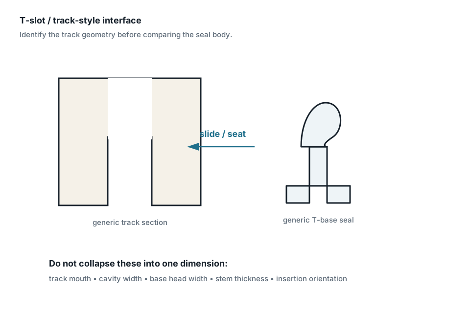
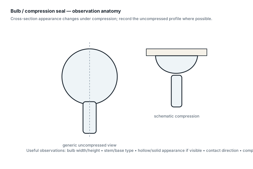
Bulb body is joined to a base whose cross-section slides into a matching slot/carrier. This page identifies a generic family and the measurements needed to compare sites; it does not identify an exact replacement.
Generic profile family supportedExact replacement fit not checkedwindow · door
Identification snapshot
- Subtype
- T-slot bulb extrusion
- Contact mode
- compression
- Seal body
- bulb
- Mount/interface
- T-slot / slide-in base
- Common terms
- T-slot bulb, T-slot weatherseal, slide-in bulb seal
- Typical intent
- hung/sliding/casement window and selected door systems
Measure before comparing
| Measurement / observation | What to record | Capture rule |
|---|---|---|
| T-base width | base backing width | Measure directly when possible; preserve original value/unit and uncertainty. |
| neck width | measurement notes (supplemental dimension; no dedicated Reference field) | Measure directly when possible; preserve original value/unit and uncertainty. |
| overall profile height | overall profile height | Measure directly when possible; preserve original value/unit and uncertainty. |
| bulb width/reach | measurement notes (supplemental observation; preserve raw label) | Measure directly when possible; preserve original value/unit and uncertainty. |
| orientation | measurement notes + photo orientation | Measure directly when possible; preserve original value/unit and uncertainty. |
Do not infer: Do not map T-slot to garage-door T-end; similar letter naming does not establish interchangeable geometry. No exact product compatibility, OEM identity, material chemistry, generation or supersession is implied.
Measurement workflow
- Stabilize the sample without stretching or deliberate compression.
- Choose and record the mounting/base datum.
- Record the tool and actual resolution before dimensions.
- Measure the base/interface before the soft sealing element.
- Capture relaxed geometry with minimal pressure.
- Measure the receiver separately when accessible.
- Record contact motion, insertion/compression direction, sample condition and uncertainty.
- Keep compatibility separate: geometry may narrow sites but does not prove fit.
Provenance
Source-backed evidence only. This page does not broaden the scope of the cited sources.
- Source — Ultrafab, T-Slot Extruded Seals
https://www.ultrafab.com/product/t-slot-extruded-seals/
Supports: T-slot as an insertion/interface family for extruded bulb profiles in window applications. · accessed 2026-10-07 - Source — Ultrafab, Multi-Hollow Bulb Seals
https://www.ultrafab.com/product/multi-hollow-bulb-seals/
Supports: Hollow/multi-hollow bulb compression body; T-slot, kerf and adhesive-backed interface options. · accessed 2026-10-07
Scope rule: Measurements, generic profile identification and exact replacement fit are kept separate. Use cited sources and your receiver geometry before making a fit decision.
Useful next steps
- Compression Weatherstrip Profiles — Profile family
- Measure Bulb & Compression Weatherstrip — Measurement guide
- Window Weatherstrip Identification — Application guide
- Door Weatherstrip Identification — Application guide
- Weatherstrip Terminology Guide — Terminology guide
- Methodology — Methodology